
IVCAD Suite Simulation
Run Stability Analysis of MMIC Circuits, Perform System Simulation using behavioral models
Simulate Virtual Data That Mirrors the Real World
There are many solutions for simulating the performance of radio frequency circuits or systems. However, without accurate models, even the best simulators won't reveal the true performance of designs. IVCAD Simulation is a tool designed to fully exploit the unique capabilities of the models and analysis tools provided by IVCAD Modeling.
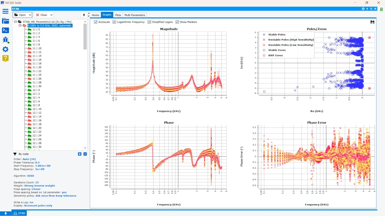
For power amplifier design, STAN is the benchmark tool for analyzing the stability of radio frequency circuits designed with accurate transistor models. This allows designers to optimize performance without risking unwanted signals.
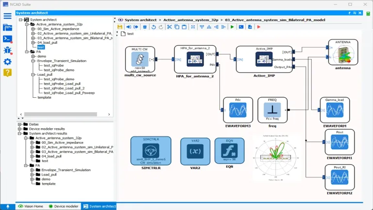
System architects designing complex RF communication systems can take advantage of IVCAD's schematic editor, RF signal generation and analysis tools, as well as frequency-domain and transient envelope CW simulation engines. These allow them to virtually design and validate concepts, drawing on various areas of expertise in digital engineering, analog design, antenna integration, etc.
IVCAD Suite Simulation - IVN
- Run Stability Analysis of MMICs
- Perform System Simulations using Behavioral Models
Why is an RF system simulator crucial?
Modern communication systems use new architectures and technologies that significantly increase the transmission speed of wireless radio frequency (RF) and microwave communications, opening the door to new opportunities that will transform our connected world: automotive driving, e-healthcare, augmented reality, collaborative robots, and many other applications.
Existing electronic design automation (EDA) software tools used to design wireless communication systems are not comprehensive and accurate enough to meet this new challenge. Currently, to overcome this limitation, equipment manufacturers:
- use experimental characterization during the design phase, which is time-consuming and requires costly test campaigns;
- use different simulators to address different phenomena (thermal, mechanical, electromagnetic) without interaction between them.
This results in a significant difference between simulation and experimental results, which can lead to launch delays and additional costs per run.
SIMULIA IVCAD modeling suite enable to anticipate the true specifications of RF systems made of active and passive circuits.
Optimize the Circuit's Performance for Integration into a System
IVCAD Suite Modeling (IVN) is naturally connected to the IVCAD Suite Modeling (IVM) modeling tool. This allows the full use of the added value of the unique models provided by the suite.
This makes it possible to simulate different types of complex RF system architectures, assessing the overall impact each circuit could have.
This also allows MMIC designers and system engineers to collaborate as a team. Indeed, thanks to this tool, the person in charge of designing the circuit can simulate the performance of their design using a circuit simulator and transform these data files into an accurate equivalent behavioral model. This model can then be used by the system engineer to assess the overall impact this design will have, for example, during performance optimization using digital predistortion.
If the overall performance is not satisfactory, the system engineer will indicate to the designer that the circuit still needs to be refined, even before the circuit is produced, thus shortening the development cycle during the project, and allowing better collaboration between the teams, for optimal overall performance.
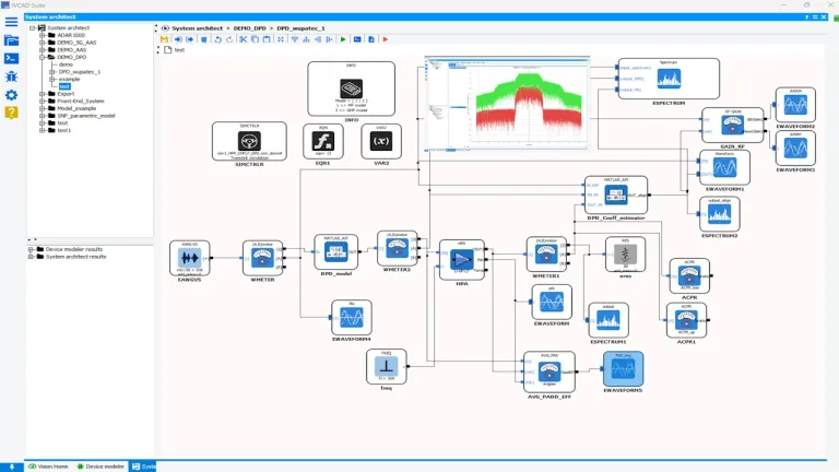
Estimate Performance of Power Amplifiers Once Linearized
The increasing complexity of wireless systems requires in-depth and detailed simulation of RF power amplifiers using wideband signals. IVCAD Simulation Suite (IVM) enables high-speed, signal-quality simulations to reveal the performance of the device under test (DUT) powered by a wideband modulated signal.
With the IVCAD front-end's signal library, it is possible to adjust the modulation with the appropriate parameters and generate an IQ waveform using the waveform generator.
System designers can optimize linearity using known algorithms (MP, GMP, etc.) or implement their own intellectual property to optimize amplifier linearity, via dynamic linkages with third-party applications, to simulate:
- Adjacent Channel Power Ratio (ACPR)
- Error Vector Magnitude (EVM) - with the signal analyzer only
- Complementary Cumulative Distribution Function (CCDF) - with the signal analyzer only
- Peak-to-Average Power Ratio (PAPR) - with the signal analyzer only
- Spectrum
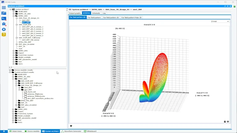
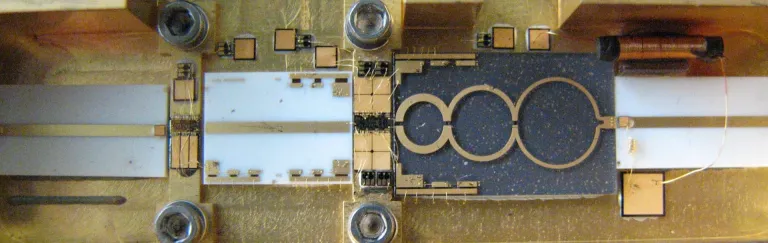
Simulate interactions between RF Front-Ends and Antennas
Active antennas used in communications systems consist of several radiating elements.
All of these elements radiate the signal in the desired direction following a control signal, but each element also radiates in undesired directions. Due to coupling between the different antenna patches, part of the signal can also return to the front-end circuits.
The looping of this signal can then disrupt the operation of the active circuit in front of the antenna, and the overall pointing angle of the antenna can disrupt the overall operation of the active circuits to varying degrees.
These effects can be mitigated by placing isolators between the antenna and the active circuits, but this type of solution can be expensive and consume space in the equipment.
To reduce the size and cost of systems, system designers generally seek to eliminate isolators. IVCAD Suite modeling, due to the precision of the active circuit models, and the consideration of the couplings of the antenna elements, allows users to anticipate, and optimize the optimal assembly of the antenna and the front-end circuits.
Analyse and Share Your Simulation Results
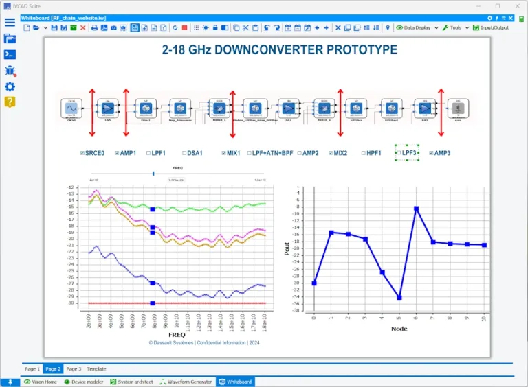
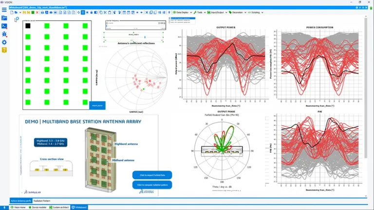
As offered by the IVCAD Front-end module (IVF), the whiteboard allows users to display the results of any simulations to analyze the results under different perspectives.
The graph templates are prepared in advance to display data related to RF system design flows.
Control actions allow users to change various types of parameters to refresh the data based on the varying conditions used during the simulation phases.
In this example, the user can change the number of patches of an active antenna and their spacing. The antenna's pointing angle is then scanned to dynamically see the impedance provided by each radiating element. This impedance variation then makes it possible to plot the performance variations of the power amplifiers feeding each radiating element during this beam scan.
This example is just one of many, and each whiteboard can be shared within the company using the Free Whiteboard tool, regardless of the license used for the simulation.
Also Discover
Unify Radio-Frequency measurement, modeling, and simulation workflows

Extract transistor models for circuit simulation and circuit models for system simulation

Conduct advanced tests on RF transistors for model extraction, begin passive load pull measurements, and test and linearize RF power amplifiers.

Waveguide measurement setups ctrl, Active Load Pull measurements, Data generation for advanced component and circuit modeling

Define RF signal testing models, start with basic measurements and create custom measurement or simulation scripts and templates for data analysis
Learn What SIMULIA Can Do for You
Speak with a SIMULIA expert to learn how our solutions enable seamless collaboration and sustainable innovation at organizations of every size.
Get Started
Courses and classes are available for students, academia, professionals and companies. Find the right SIMULIA training for you.
Get Help
Find information on software & hardware certification, software downloads, user documentation, support contact and services offering