Collaborative Circuit Board Designer
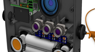
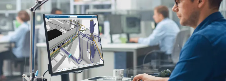
Offer the engineering virtual twin of electronic assembly board in context of MCAD design, reducing time to market thanks to virtual mechanical integration.
Role
A Powerful End-to-end Process for All Electrical Designers
Modern industry faces many challenges as it strives to meet the demands of a market seeking smarter products and energy efficient solutions. The increasing connectivity and autonomy of products and services, coupled with their growing complexity, necessitate compliance to strict regulatory standards and new types of requirements. Simultaneously, production methods and techniques are undergoing significant changes, fostering a pressing need for collaboration and innovation. In this context, the integration of software, electronics and electrical engineering has become paramount in product development.
3DEXPERIENCE CATIA Electrical Engineering Roles empower professionals with a comprehensive end-to-end process, enabling to design, install and manufacture disruptive electrical systems that are poised to tackle the challenges of the future with confidence.
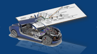
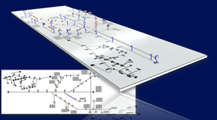
At the outset of the design process, a comprehensive analysis of systems architectures, equipment, and signal lists can be achieved with the right tools. 3DEXPERIENCE CATIA offers a solution through the development of a collaborative 3D architectural mock-up to draft system zones or packaging, equipment and interface definitions, signal information, and engineering rules. Leveraging cutting-edge routing and path-finding technology, it is now possible to optimize the paths of high-level signals within the mechanical environment. This advanced capability allows for accurate design predictions.
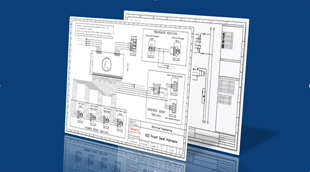
Our comprehensive solution offers a specialized logical design role with a wide array of tools, to effortlessly create precise net and wiring definitions and draw intricate electrical schematics within the robust framework of the 3DEXPERIENCE platform. Engineers can define and incorporate every object with meticulous detail, ranging from major equipment to the tiniest splices, including connectors, terminal blocks, wires, and cables. Integration also leverage the power of CATIA technologies to streamline the creation of electrotechnical diagrams that comply with international standards, facilitating the design process for electrical cabinets. Our innovative solution goes beyond manual design. By utilizing imported or generated net and wiring definitions, you can effortlessly generate complete sets of diagrams with just a few clicks.
Our intelligent system adheres to predefined parameters and design rules, ensuring the creation of compliant representations of entire systems in a fraction of the time. With our software, you have the power to design accurate and detailed electrical schematics, whether you prefer a hands-on approach or the convenience of automated generation. Experience efficiency and precision in one seamless package.
CATIA Electrical Roles enable smooth transitions between electrical system design steps. From architecture to net, net to wire, logical definition to physical installation, and detailed design to manufacturing, our assistant interfaces provide clear synchronization status and aid decision-making. Equipment, connectors, and wires are positioned automatically, allowing designers to focus on detailed completion, support placement, branch creation, wire routing, protection, and bundle geometry. Harness 3D design directly inputs into manufacturing and drawing generation, eliminating intermediaries. Streamline your design process with effortless transitions.
CATIA Electrical Engineering software products are packaged as Roles to get you up to speed faster and work more efficiently with all needed applications available at your fingertips. Select a package that corresponds to your role in an organization.
Offer the engineering virtual twin of electronic assembly board in context of MCAD design, reducing time to market thanks to virtual mechanical integration.
Role
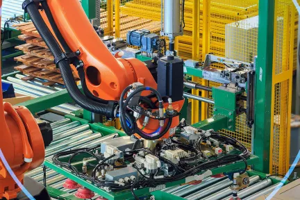
Optimize the physical design of wire harnesses and cable systems in context of the complete product and prepare quickly high quality manufacturing documentation
Role
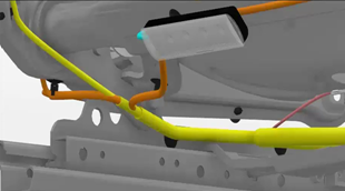
An integrated 3D electrical development environment which enables the physical design of wire harnesses and cabling in the context of the complete product
Role
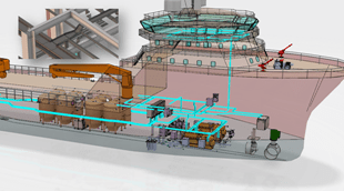
An integrated 3D electrical development environment which enables the physical design of cabling and cable tray systems in context of the complete product
Role
Save costly development time by optimizing the quick preparation of high quality manufacturing documentation
Role
Create discipline-specific intelligent schematics for wiring, cabling, piping/tubing and HVAC systems
Role
The Cutting Edge of Electromechanical Integration
Electrical Schematic and Wiring Diagrams
The world of Electrical System is changing. Discover how to stay a step ahead with CATIA
Virtual Twin for Electrical & Fluid Systems Design Process
EBooks
Manage traceability along the entire electrical systems life-cycle
E-seminars
The SE commision of UCODS is pleased is pleased to announce its next webinar : "From Needs to Tests" which will take place on October 14, 2026 at 05:00 pm (French Time)Register at the following link:https://www.ucods.eu/event/from-needs-to-tests-56/registerWebinar Description : This webinar showcases a unified, collaborative approach from requirements management (TRM) to test management (VRP)
CATIA MBSE CYBER SYSTEMS
This is amazing new integration sample of flexible web based UI. Based on highly configurable ALM web based solution - Tuleap. Solution is for non-modeler to capture business data and automatically transition it to world wide recognized standard of the model in OMG UAF. Solution is covering UAF strategy, operational, resources model generation including elements, relations and diagrams. OverviewT
CATIA MBSE CYBER SYSTEMS
Hi,Is there a published format of a Cameo Collaborator Document? For example, is it possible to access the links with a collaborator document? How is the collaborator document stored? Thank you, Maria DAgostino
CATIA MBSE CYBER SYSTEMS
SysML v2 gives shapes, coordinate frames and units a meaning that tools can reason over. Lets overview SysML v2 geometry capabilities from a ten-line car envelope to requirements that are rechecked in CATIA / 3DEXPERIENCE.Full demo:https://youtu.be/4SHATeLi2o8 Note: All figures are renders and screenshots from running models.An orbital station of about 150 parts. Every shape and every position i
CATIA MBSE CYBER SYSTEMS
Design End-to-end, compliant Fluid Systems in a Collaborative Product Development platform
A Comprehensive Set of Engineering Roles Integrated in a Seamless Design Process
Speak with a CATIA expert to learn how our solutions enable seamless collaboration and sustainable innovation at organizations of every size.
Courses and classes are available for students, academia, professionals and companies. Find the right CATIA training for you.
Find information on software & hardware certification, software downloads, user documentation, support contact and services offering